KRISS Vector Fire Control Group **UPDATED 4-2-13**
+4
Solscud007
buddybaja
Kiptroloxe
RubbaDubbaBubba
8 posters
Page 1 of 1
 KRISS Vector Fire Control Group **UPDATED 4-2-13**
Kriss V Fire Control Group (FCG) for .45 carbine
This is not a Holy Grail of the Kriss V, This is for educational purposes and may vary
depending on you particular model. Notes are from my weapon.
The FCG is fairly simple, it has 27 parts consisting of.
I do not know the nomenclature of the Kriss parts, so I MAKADA my own names.
You'll get the point, I think?
Parts of the Fire Control Group (FCG)
1 - Frame

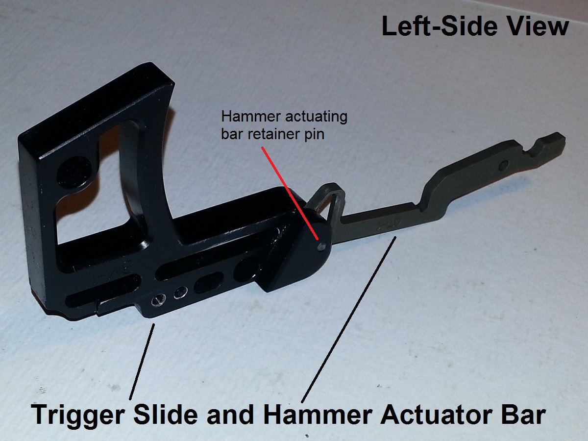
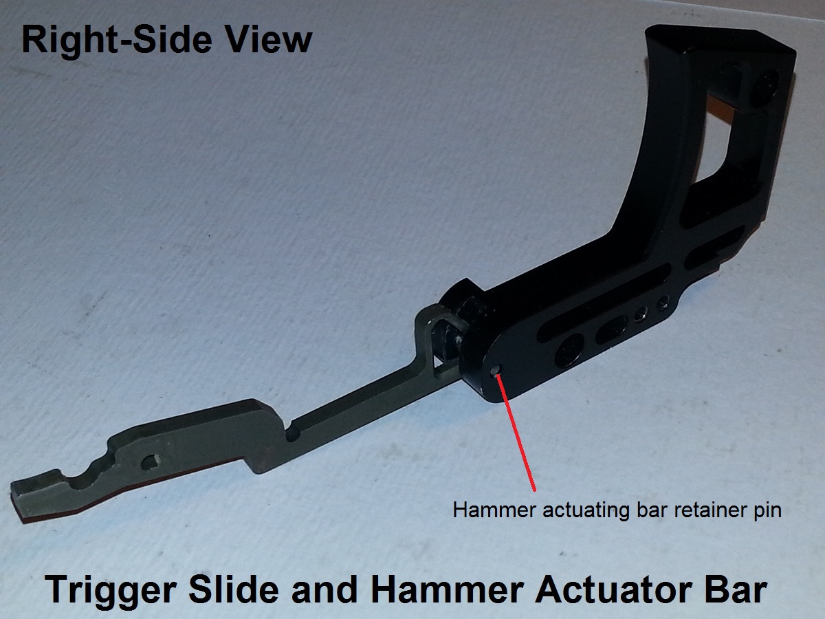
1 - Trigger slide
1 - Hammer actuating bar
1 - Hammer actuating bar retainer pin
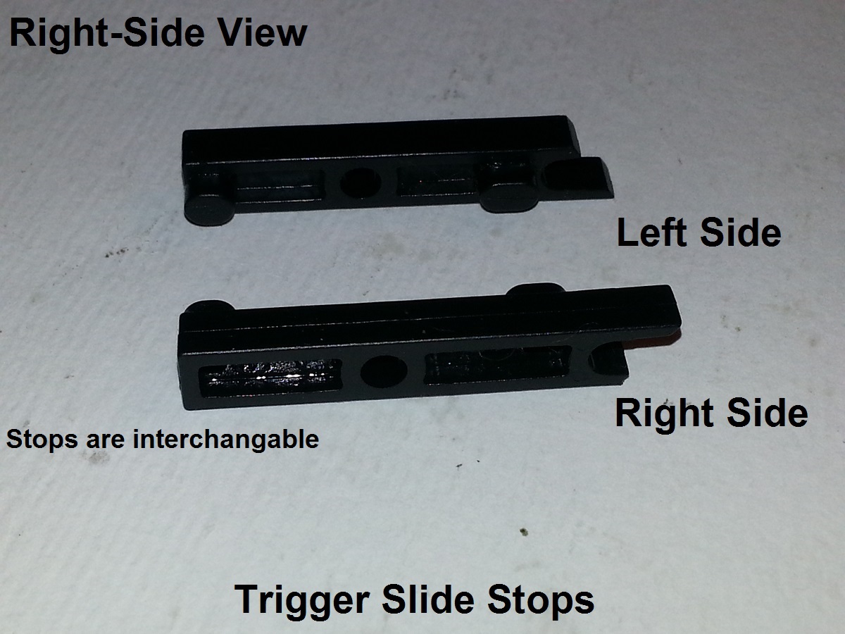
1 - Left trigger slide stop
1 - Right trigger slide stop

2 - Trigger slide retainer pins
2 - Trigger slide return springs
2 - Trigger slide return spring screws
2 - Trigger frame return spring screws

1 - Safety selector block
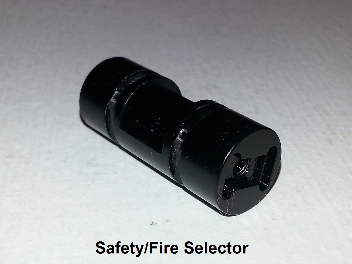
1 - Hammer actuating bar tension spring/Safety selector retainer clip

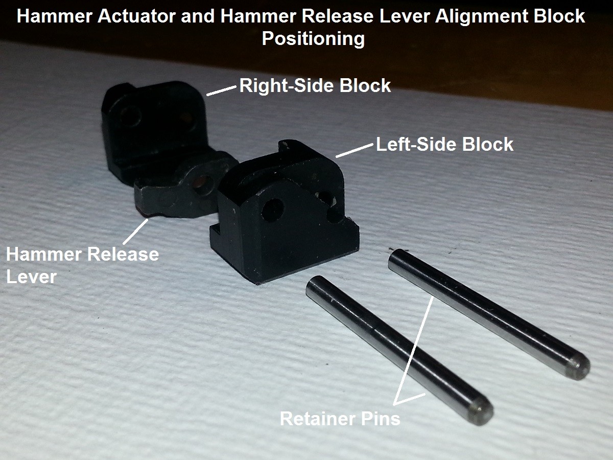
1 - Right side Hammer actuator bar/Hammer release lever block
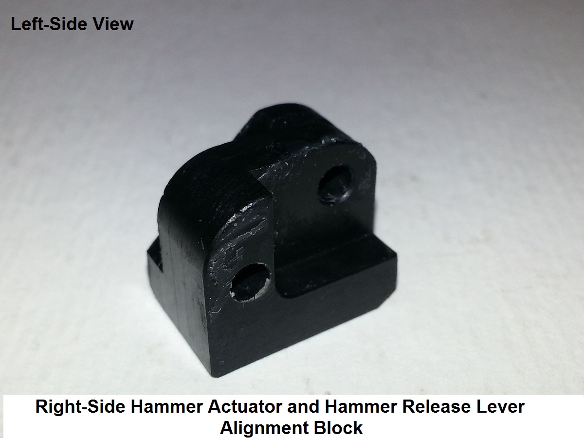
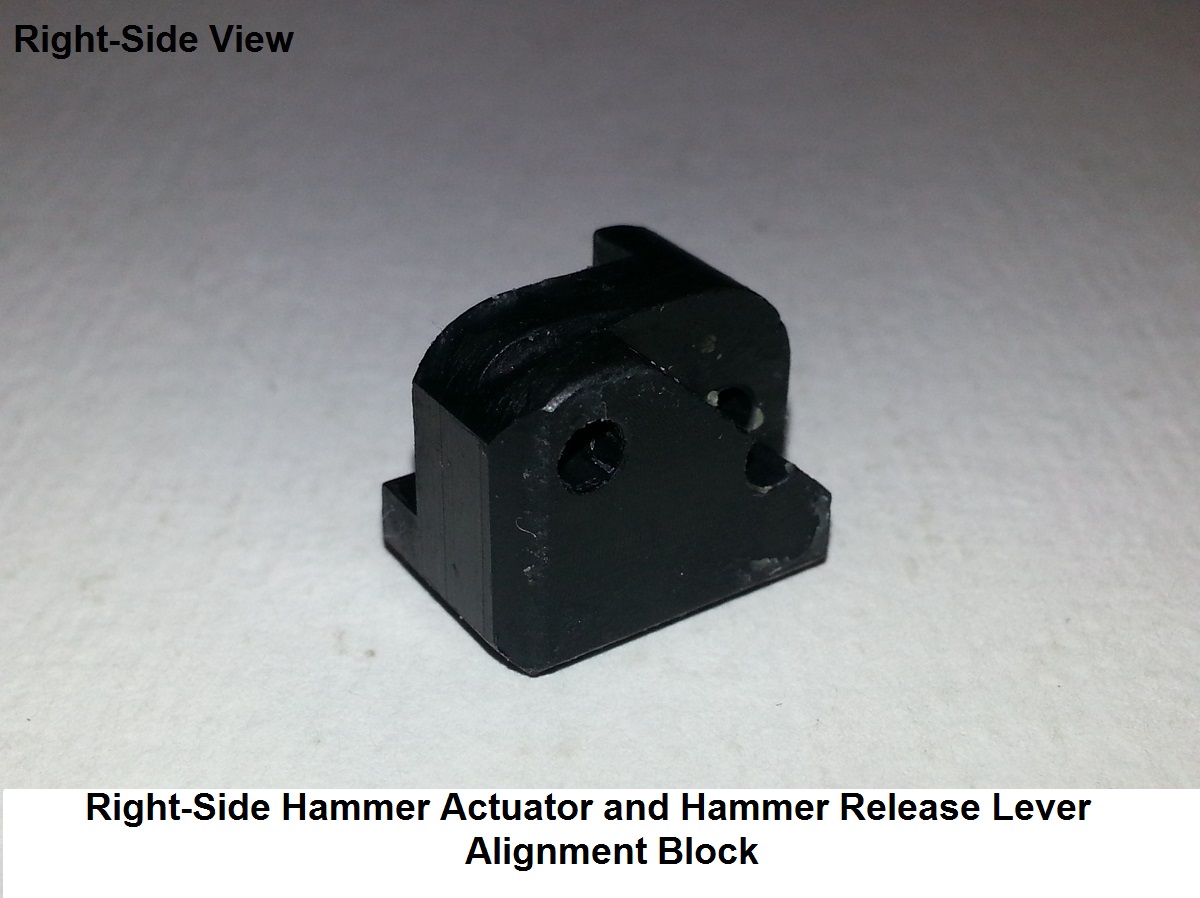
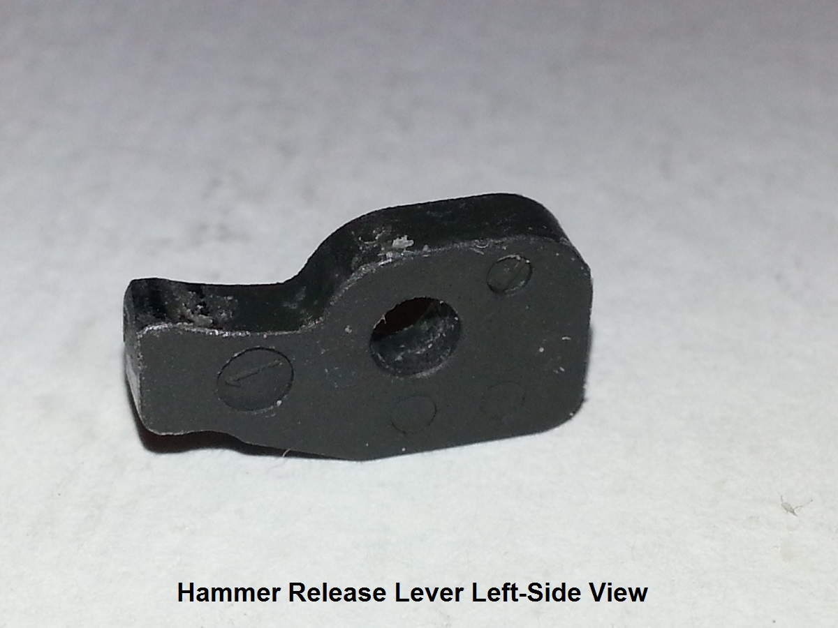
1 - Hammer release lever

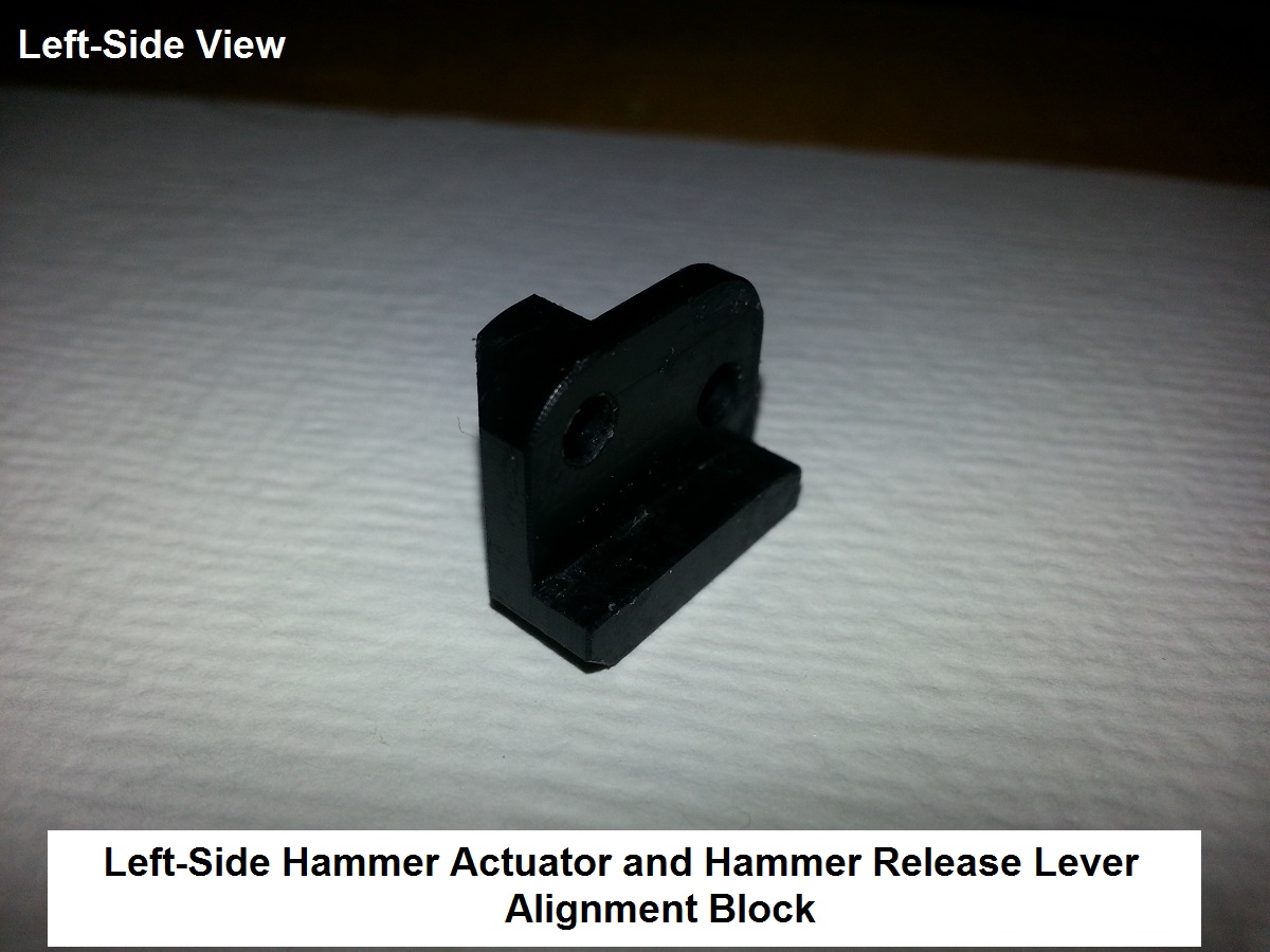
1 - Left side Hammer actuator bar/Hammer release lever block
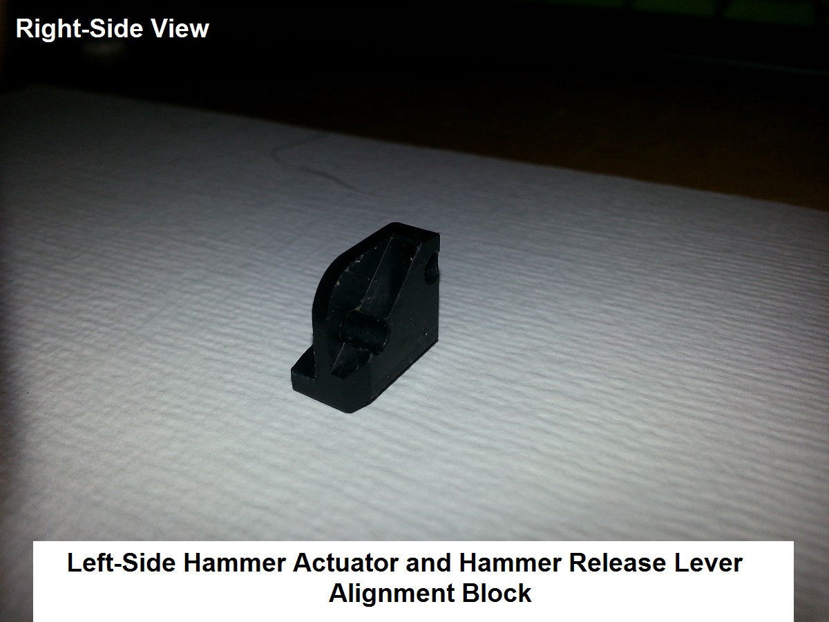
1 - Hammer actuator bar/Hammer release lever block and retainer pin
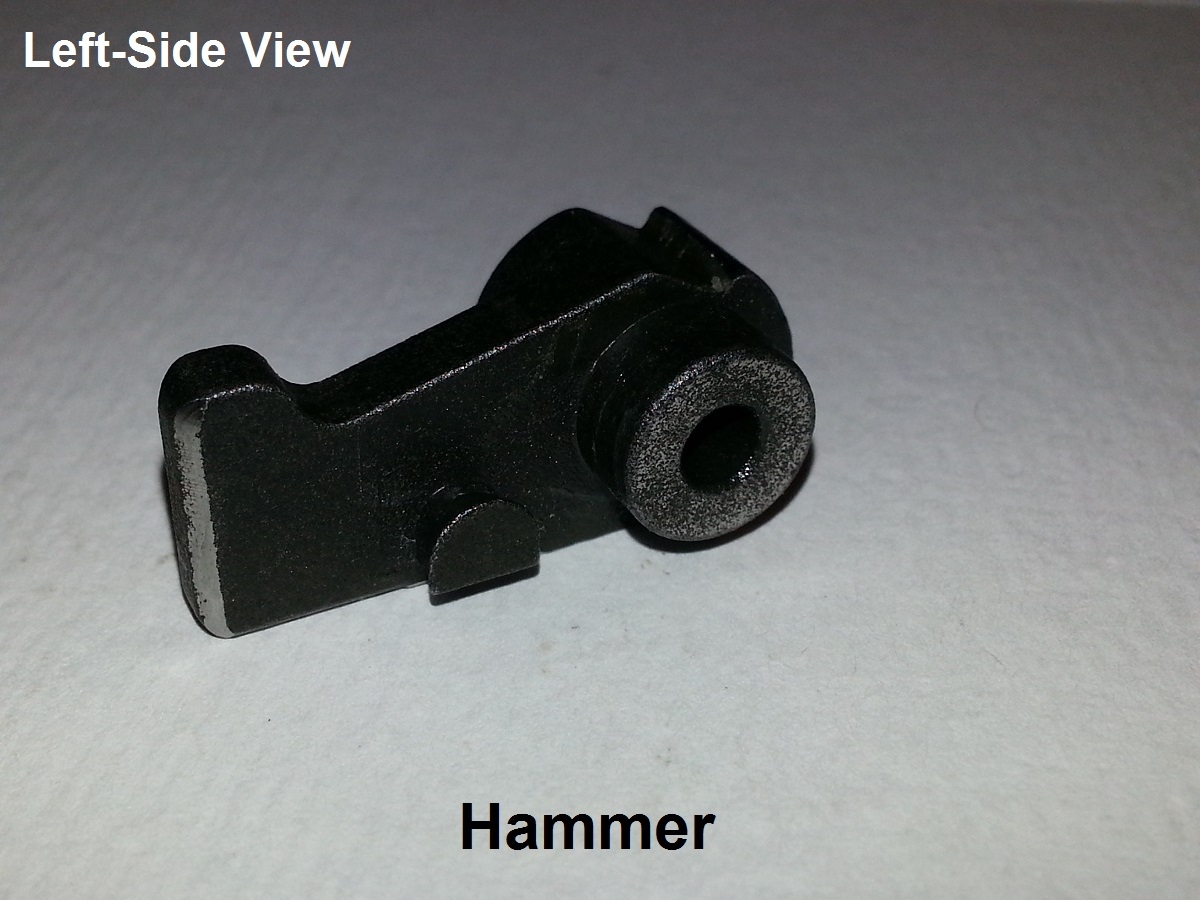
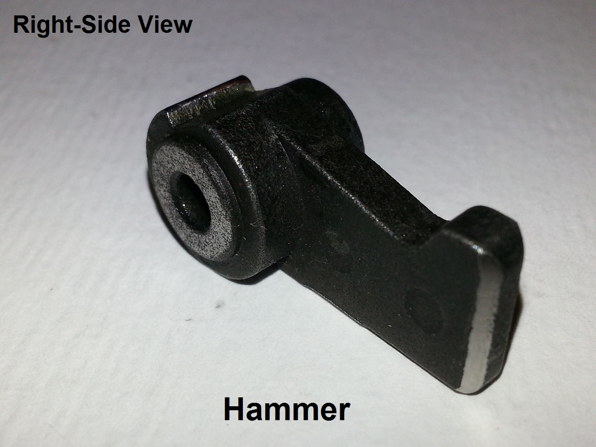
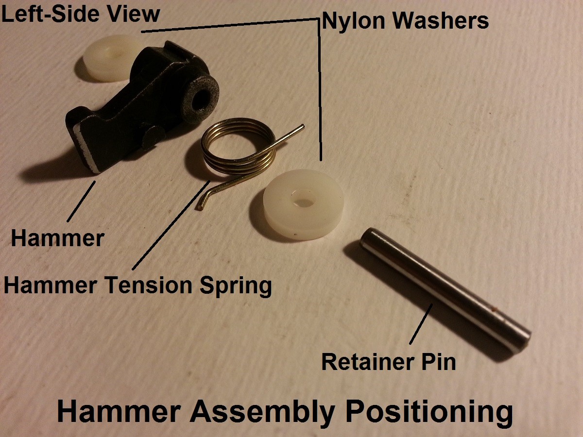
1 - Hammer
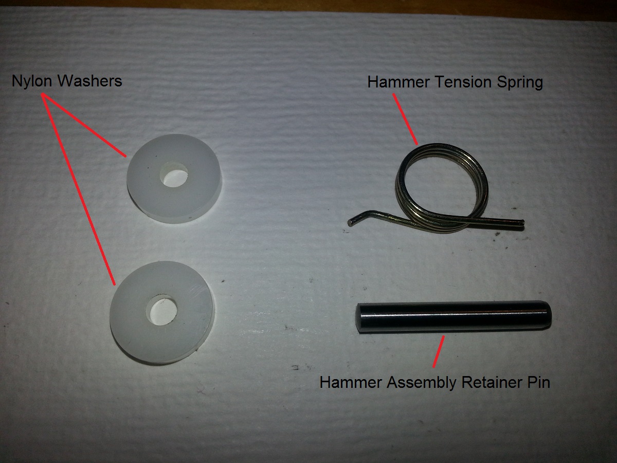
1 - Hammer tension spring
2 - Nylon washers
1 - Hammer assembly retainer pin
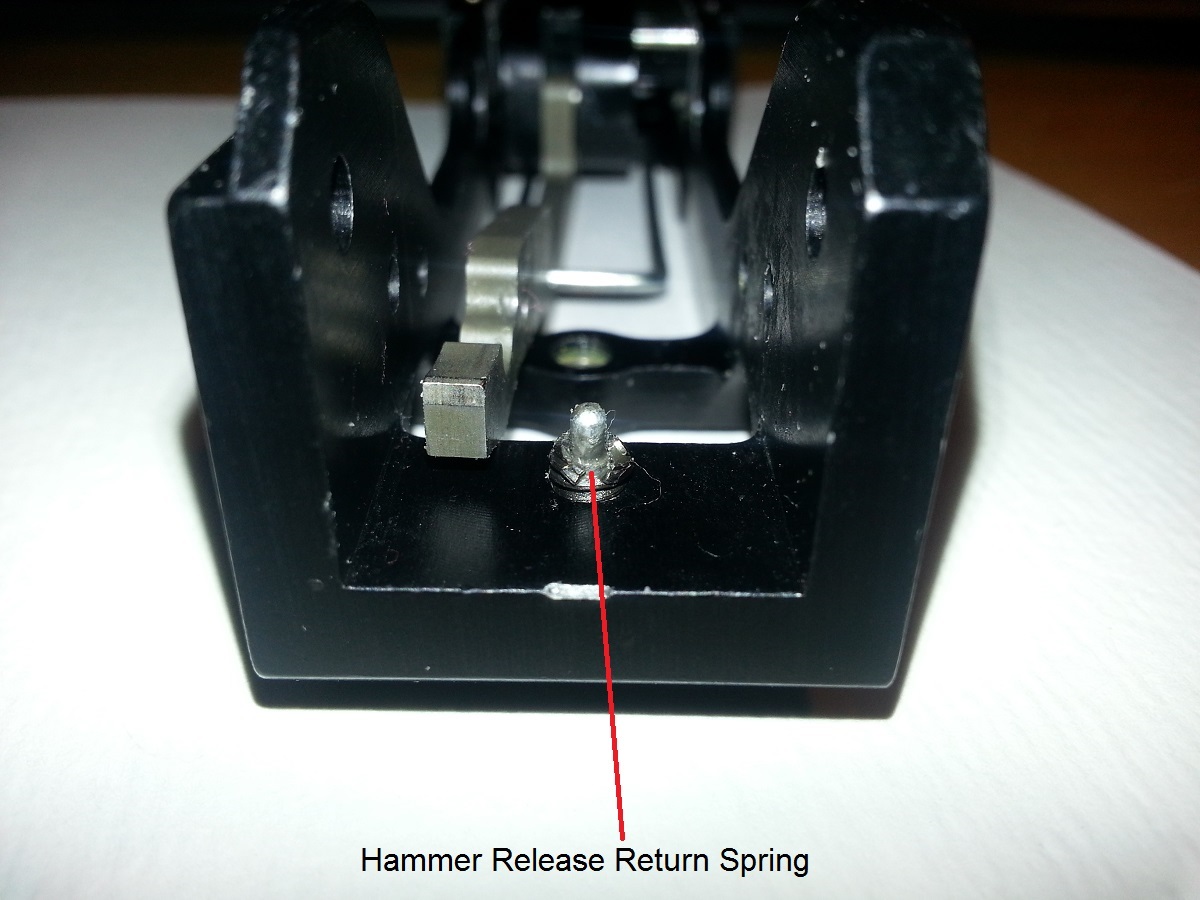
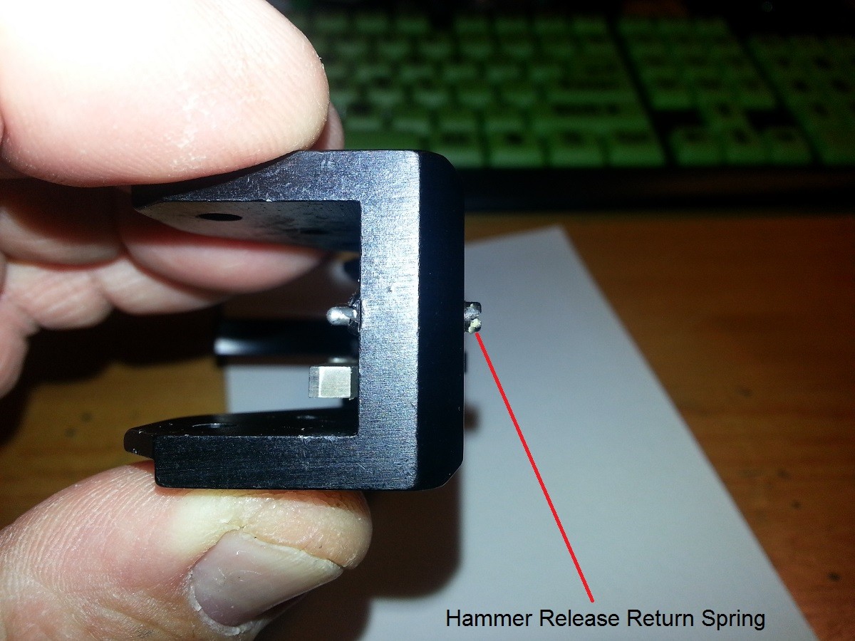
1 - Hammer release lever return spring
============================================================
Attached is a rough and dirty look at the Fire Control Group of my Kriss V .45 Carbine.
My serial number is in the 45C002XXX close enough.
This is for educational purposes and may vary depending on you particular model.
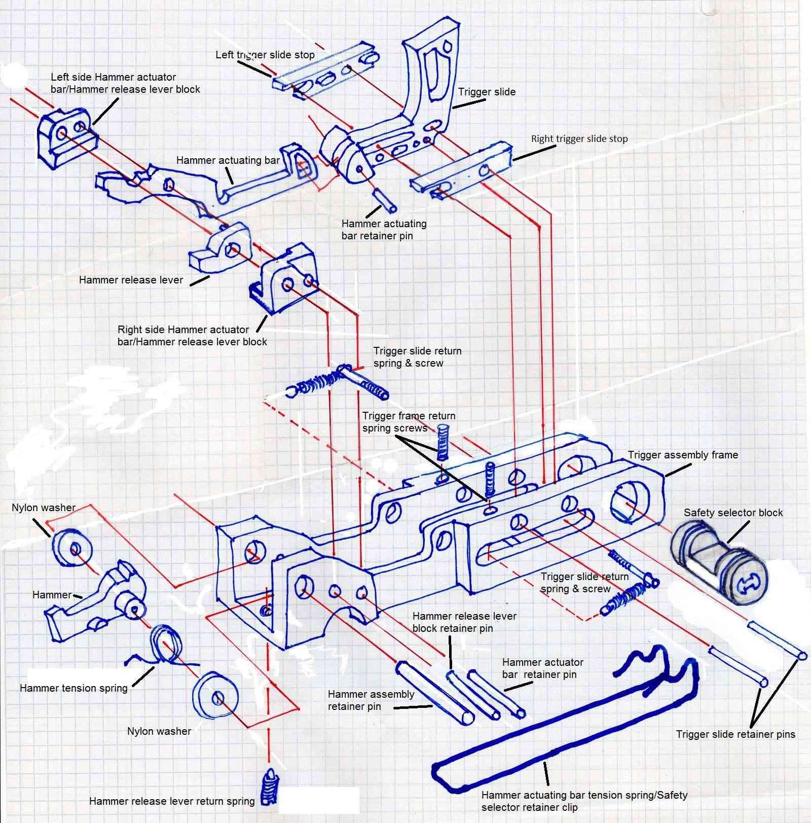
Below are pictures of the FCG:
Tools needed:
- Metric Allen key set
- 1/8" Flat blade screwdriver
- Small jewelers hammer
- Punch set
To Assemble FCG:
1 - Attach left and right trigger slide stop blocks to the trigger slide block.

2 - Place trigger slide assembly in to frame and push trigger slide retainer pins in to place.
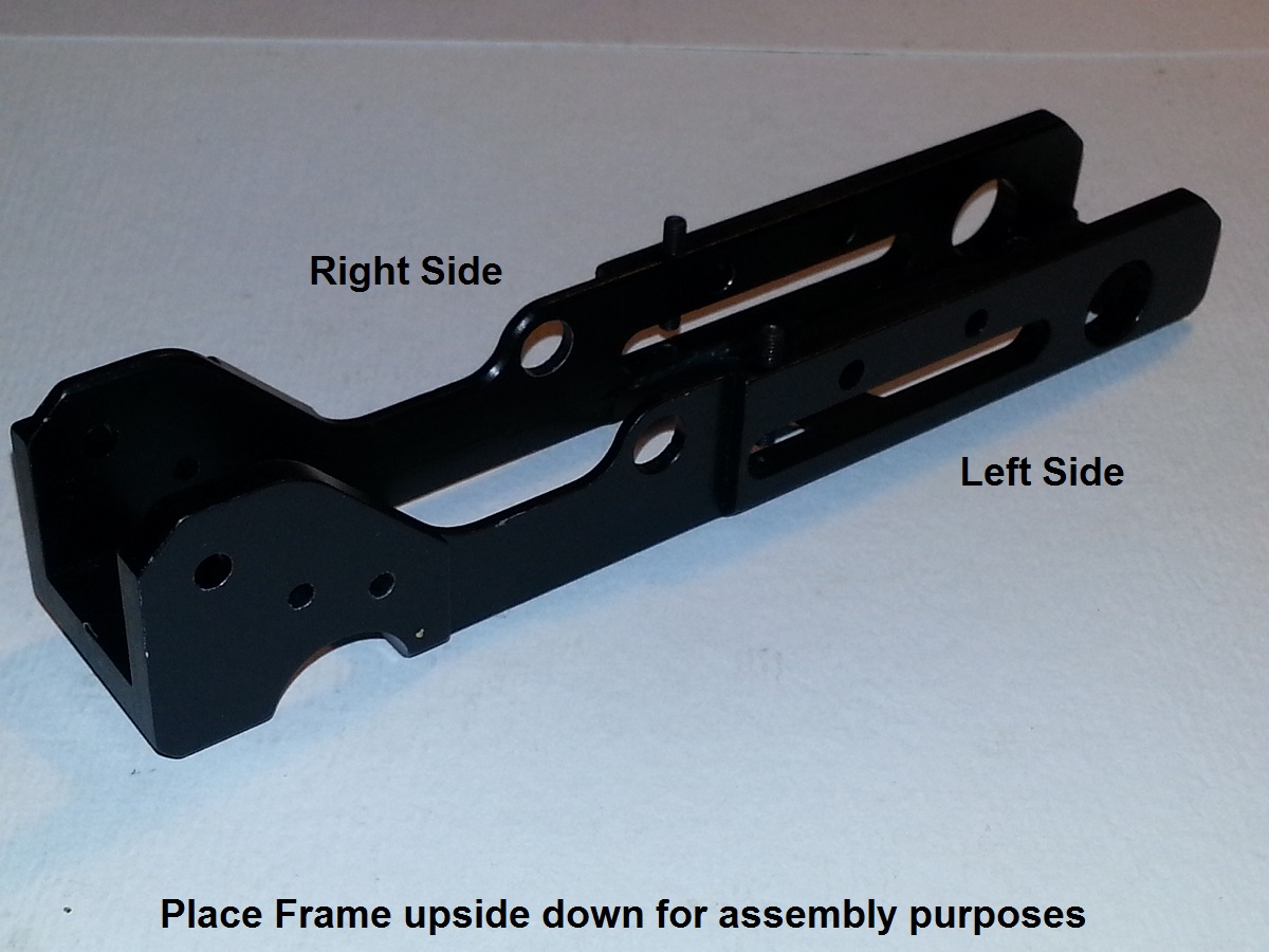

3 - Hold trigger slide return spring under trigger frame return spring screw and tighten screw
thru spring loop. This is for both sides.
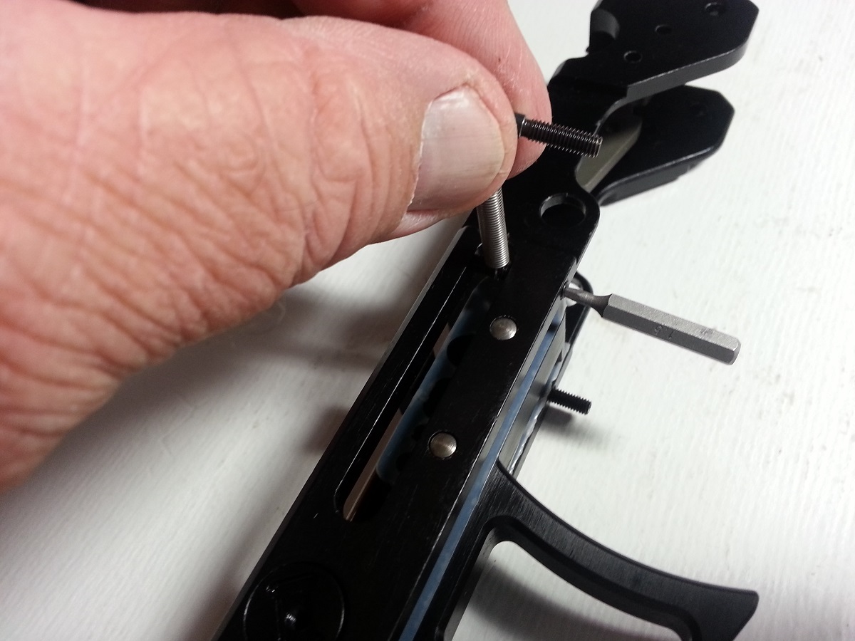

4 - On left side of frame place trigger slide return spring screw in front threaded hole and
tighten.

5 - On right side of frame place trigger slide return spring screw in the rear threaded hole and
tighten.
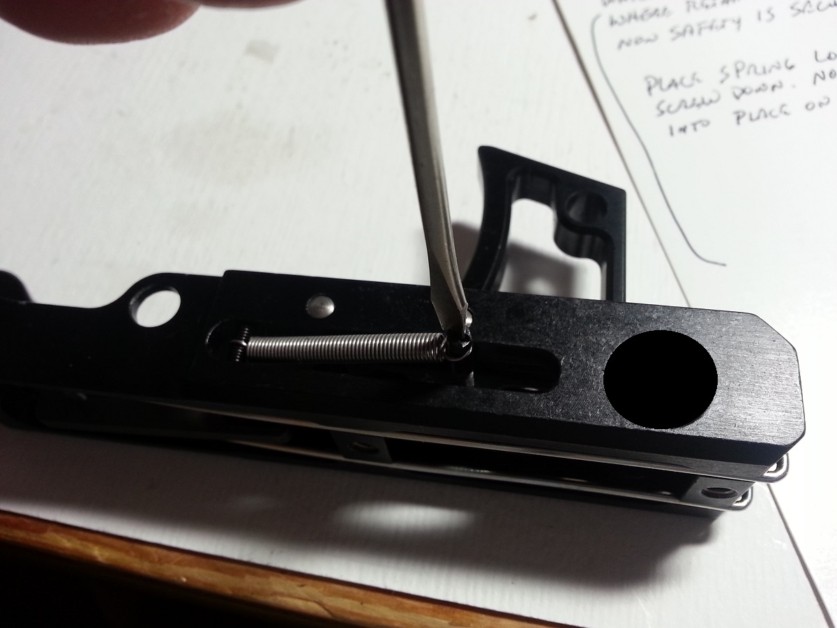
6a - Holding frame up, lift hammer actuator bar and insert hammer actuating bar tension
spring from the bottom and up and over the hammer actuating bar.
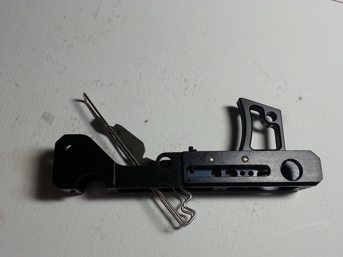
6b - Pull spring back towards the trigger.
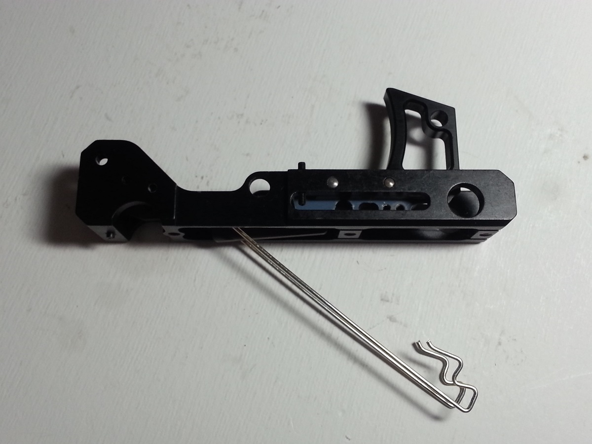
7a - Take safety selector block and insert into frame. Once in place rotate till flat part of
selector till it is facing the flat side of trigger slide. This allows you to manipulate the
hammer actuator bar for the purpose of aligning parts.

7b - The hammer actuator bar tension spring is ready to be secured. With tension spring
pulled back, set assembly down on work station and hold down.
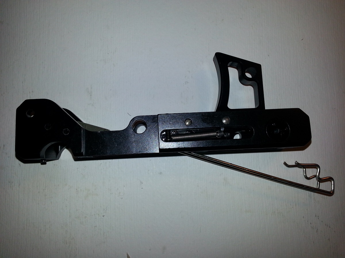
7c - With spring tabs facing safety selector block, push until spring tabs ride over the
grooves on the selector block.
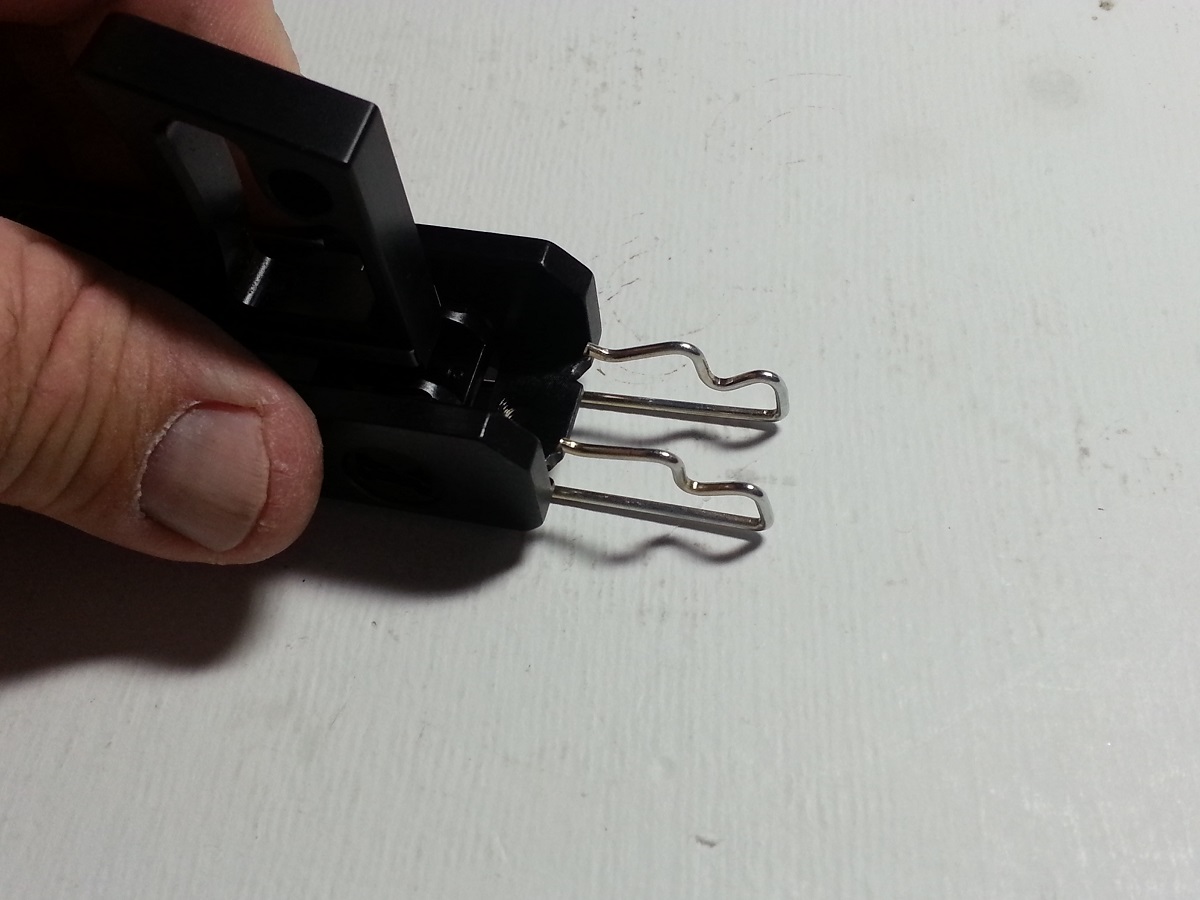
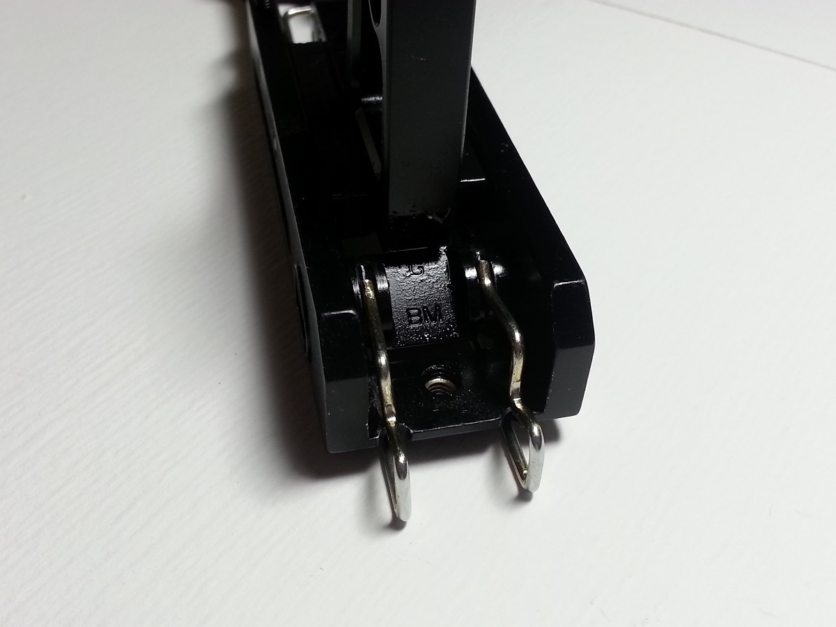
7d - Ensure that the spring is fully seated against the frame.
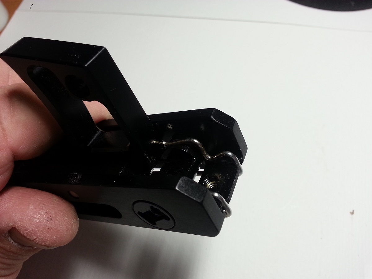
8a -Lift the hammer actuator bar and slide the Left-side alignment block in place and insert
hammer actuator bar retainer pin till flush with Hammer Actuator Bar. Lower Hammer Actuator bar.
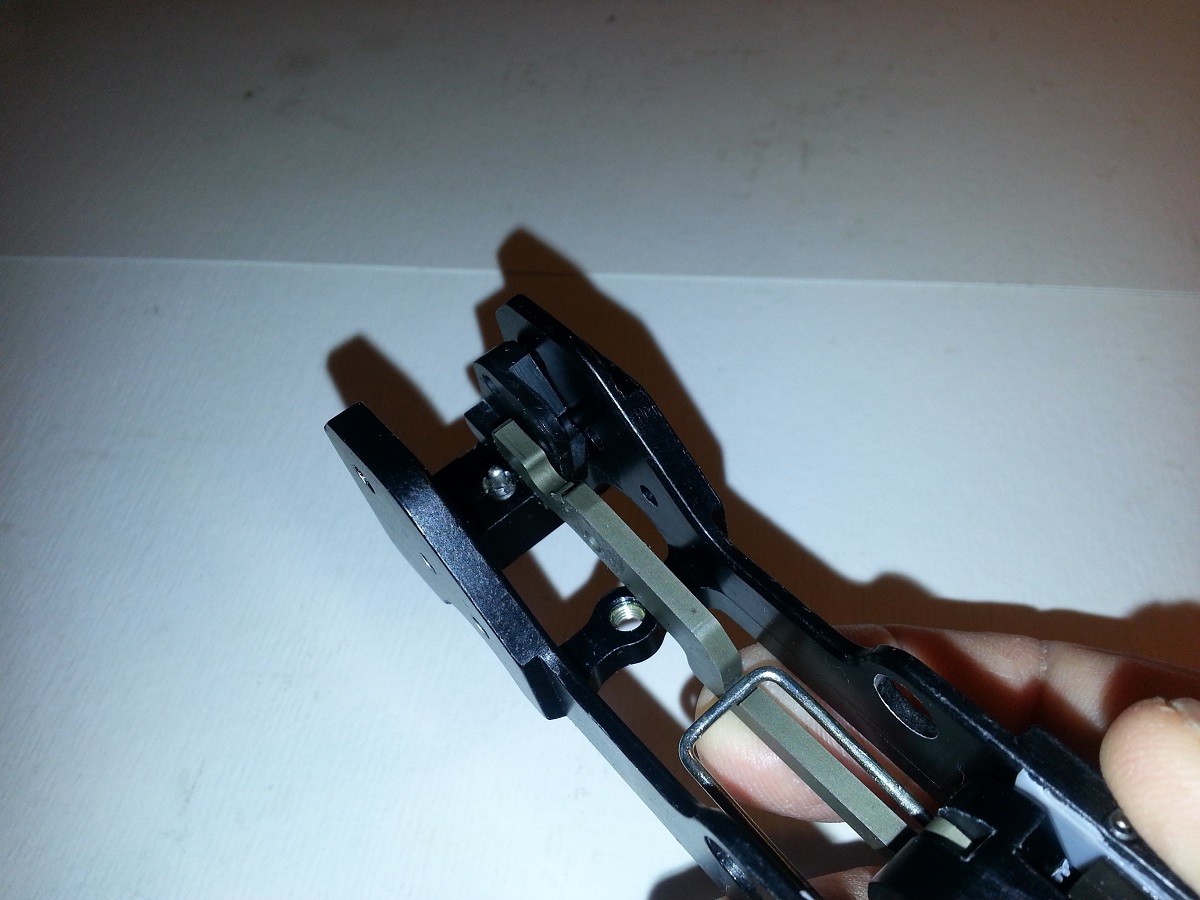
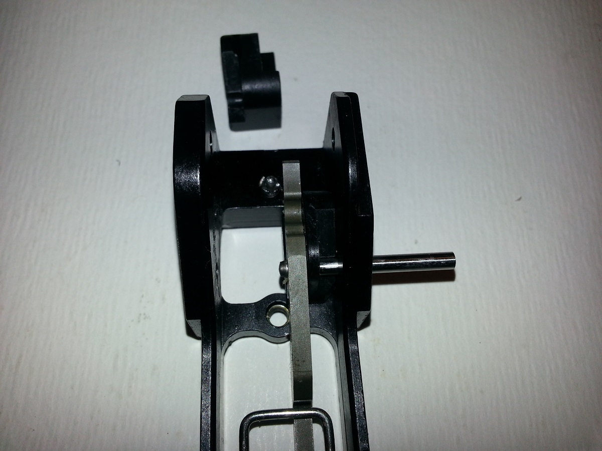
8b - Insert the Right-side alignment block and finish pushing in the retainer pin.
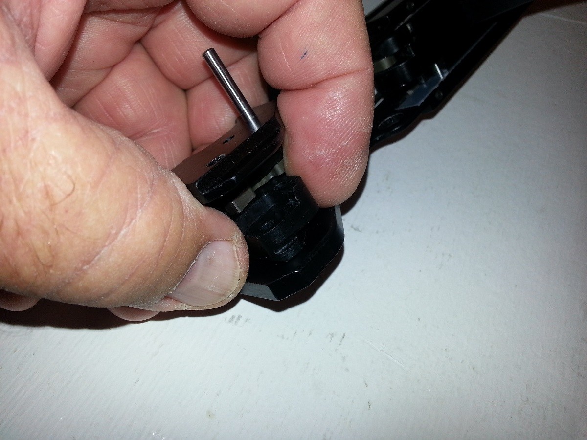
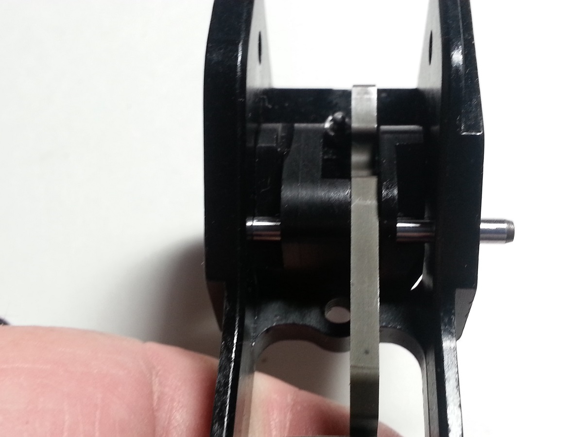
9a - Insert hammer release lever and insert hammer release lever retainer pin.
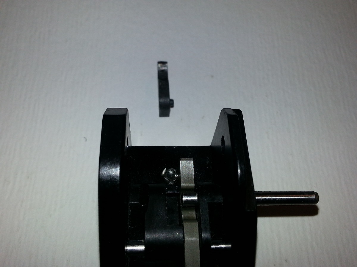
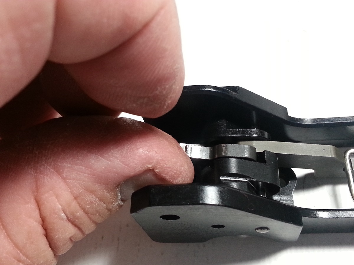
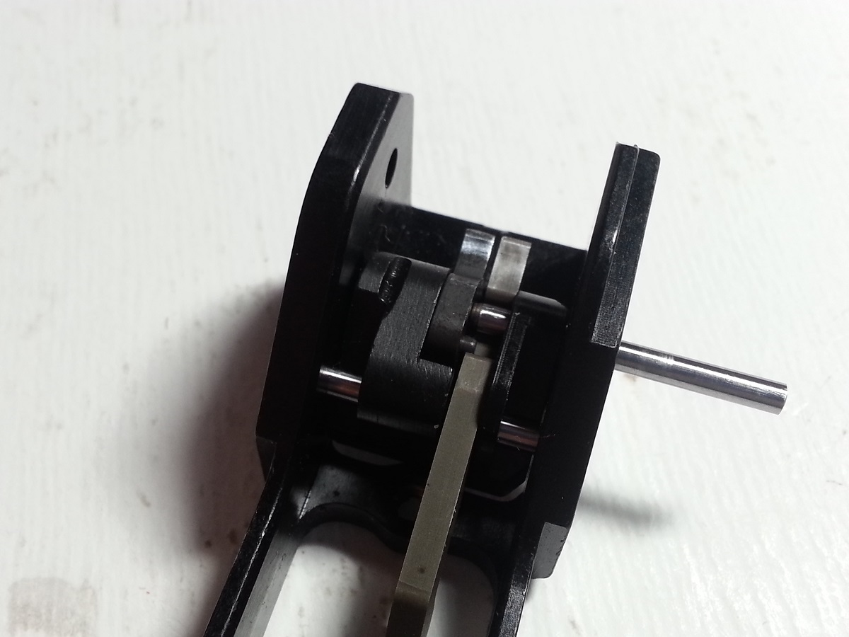

9b - Move the hammer actuator bar and observe hammer lever is operating opposite of
actuator.

9c - Insure that hammer lever return spring is not sticking and is pushing hammer lever
back up when hammer actuator bar is released.
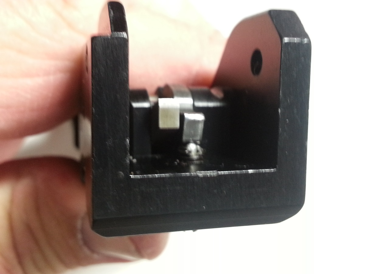
10a - Place nylon washer against the inner left side of the frame. Insert hammer
assembly retainer pin and push till flush with washer.
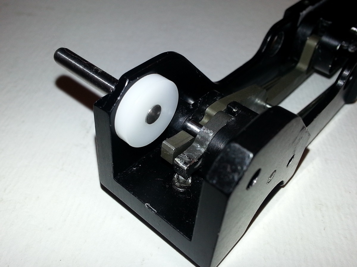
10b - Next attach hammer tension spring to hammer and place next to nylon washer,
while holding hammer and spring in place, push the retainer pin in and continue to
maintain press on hammer and spring.
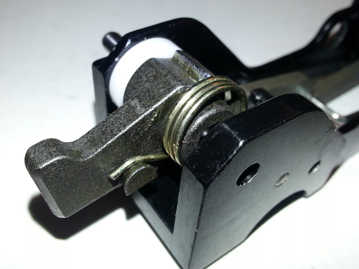
10c - Place the second nylon washer between the hammer and frame, finish pushing the
retainer pin into place.
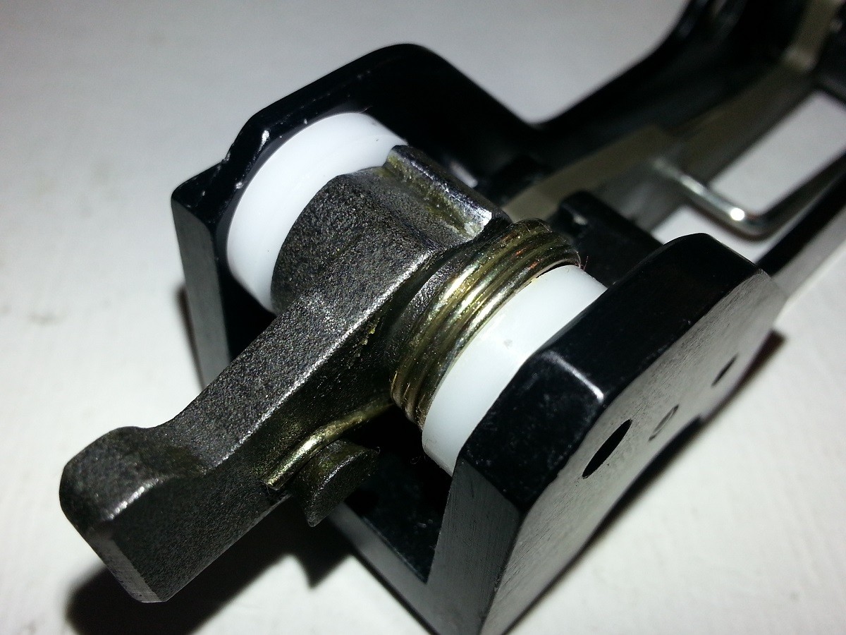
11 - Now cock and test the trigger assembly to ensure proper operation.
12 - FCG in now ready to be placed into the upper housing.
Hope this has been informative...
Leave any feedback if incorrect or you might have the correct nomenclature.
Thanks, checkout my other post:
- Well, Stipple My Grips
- Another Brass Catcher
- Another Shroudy Day
- New Gun Slinger in Town
This is not a Holy Grail of the Kriss V, This is for educational purposes and may vary
depending on you particular model. Notes are from my weapon.
The FCG is fairly simple, it has 27 parts consisting of.
I do not know the nomenclature of the Kriss parts, so I MAKADA my own names.
You'll get the point, I think?
Parts of the Fire Control Group (FCG)
1 - Frame

1 - Trigger slide
1 - Hammer actuating bar
1 - Hammer actuating bar retainer pin


1 - Left trigger slide stop
1 - Right trigger slide stop


2 - Trigger slide retainer pins
2 - Trigger slide return springs
2 - Trigger slide return spring screws
2 - Trigger frame return spring screws

1 - Safety selector block

1 - Hammer actuating bar tension spring/Safety selector retainer clip

1 - Right side Hammer actuator bar/Hammer release lever block


1 - Hammer release lever


1 - Left side Hammer actuator bar/Hammer release lever block


1 - Hammer actuator bar/Hammer release lever block and retainer pin

1 - Hammer


1 - Hammer tension spring
2 - Nylon washers
1 - Hammer assembly retainer pin


1 - Hammer release lever return spring


============================================================
Attached is a rough and dirty look at the Fire Control Group of my Kriss V .45 Carbine.
My serial number is in the 45C002XXX close enough.
This is for educational purposes and may vary depending on you particular model.

Below are pictures of the FCG:
Tools needed:
- Metric Allen key set
- 1/8" Flat blade screwdriver
- Small jewelers hammer
- Punch set
To Assemble FCG:
1 - Attach left and right trigger slide stop blocks to the trigger slide block.

2 - Place trigger slide assembly in to frame and push trigger slide retainer pins in to place.


3 - Hold trigger slide return spring under trigger frame return spring screw and tighten screw
thru spring loop. This is for both sides.


4 - On left side of frame place trigger slide return spring screw in front threaded hole and
tighten.

5 - On right side of frame place trigger slide return spring screw in the rear threaded hole and
tighten.

6a - Holding frame up, lift hammer actuator bar and insert hammer actuating bar tension
spring from the bottom and up and over the hammer actuating bar.

6b - Pull spring back towards the trigger.

7a - Take safety selector block and insert into frame. Once in place rotate till flat part of
selector till it is facing the flat side of trigger slide. This allows you to manipulate the
hammer actuator bar for the purpose of aligning parts.

7b - The hammer actuator bar tension spring is ready to be secured. With tension spring
pulled back, set assembly down on work station and hold down.

7c - With spring tabs facing safety selector block, push until spring tabs ride over the
grooves on the selector block.


7d - Ensure that the spring is fully seated against the frame.

8a -Lift the hammer actuator bar and slide the Left-side alignment block in place and insert
hammer actuator bar retainer pin till flush with Hammer Actuator Bar. Lower Hammer Actuator bar.


8b - Insert the Right-side alignment block and finish pushing in the retainer pin.


9a - Insert hammer release lever and insert hammer release lever retainer pin.


9b - Move the hammer actuator bar and observe hammer lever is operating opposite of
actuator.

9c - Insure that hammer lever return spring is not sticking and is pushing hammer lever
back up when hammer actuator bar is released.

10a - Place nylon washer against the inner left side of the frame. Insert hammer
assembly retainer pin and push till flush with washer.

10b - Next attach hammer tension spring to hammer and place next to nylon washer,
while holding hammer and spring in place, push the retainer pin in and continue to
maintain press on hammer and spring.

10c - Place the second nylon washer between the hammer and frame, finish pushing the
retainer pin into place.

11 - Now cock and test the trigger assembly to ensure proper operation.
12 - FCG in now ready to be placed into the upper housing.
Hope this has been informative...
Leave any feedback if incorrect or you might have the correct nomenclature.
Thanks, checkout my other post:
- Well, Stipple My Grips
- Another Brass Catcher
- Another Shroudy Day
- New Gun Slinger in Town
Last edited by RubbaDubbaBubba on Tue Apr 02, 2013 7:03 pm; edited 2 times in total
RubbaDubbaBubba- Posts : 9
Join date : 2013-03-15
Age : 34
 Re: KRISS Vector Fire Control Group **UPDATED 4-2-13**
Great Exploded View!!!! For now I think you are missing a few pics.
I happen to have these from a recent cleaning.


I happen to have these from a recent cleaning.



Kiptroloxe- Posts : 81
Join date : 2013-01-03
 Re: KRISS Vector Fire Control Group **UPDATED 4-2-13**
This is very informative. Now I dont have to cheat when I clean my fcg. I rinse with water and mild soap (per manual) hit with compressed air then hit with hoppes... lots of hoppes and let sit for 20. The hit with air again. Then another oiling in certain spots. Lol.
buddybaja- Posts : 101
Join date : 2013-02-26
 Re: KRISS Vector Fire Control Group **UPDATED 4-2-13**
Great Pictures and nice detail
I think we should move this to the trigger job and info thread
I think we should move this to the trigger job and info thread
 Trigger assembly
Sweat great job.
toneotone- Posts : 5
Join date : 2013-01-20
Age : 63
Location : Champaign ,IL
 Re: KRISS Vector Fire Control Group **UPDATED 4-2-13**
I'll vote for CatMostFeared's comment.
"Great Pictures and nice detail
I think we should move this to the trigger job and info thread".
"Great Pictures and nice detail
I think we should move this to the trigger job and info thread".
AZ2000- Posts : 197
Join date : 2012-08-09
Location : AZ

Jedi380- Posts : 239
Join date : 2013-01-24
Location : Dayton, OH
 Similar topics
» Sig Sauer SB15 Arm Brace On The Kriss Vector SDP Pistol *Updated 9/24/14-Mod Completed*
» Rapid Fire Thompson M1A1 vs KRISS Vector SMG
» KRISS SMG Vert Grip group buy
» WTS: Kriss Vector Tactical Sling (no pin) and Vector Quick Release Slingmount Pin
» Does the Shroud for the Real Kriss Vector work for the KWA GBB Airsoft Vector?
» Rapid Fire Thompson M1A1 vs KRISS Vector SMG
» KRISS SMG Vert Grip group buy
» WTS: Kriss Vector Tactical Sling (no pin) and Vector Quick Release Slingmount Pin
» Does the Shroud for the Real Kriss Vector work for the KWA GBB Airsoft Vector?
Page 1 of 1
Permissions in this forum:
You cannot reply to topics in this forum
 Home
Home


